| The main board |
|---|
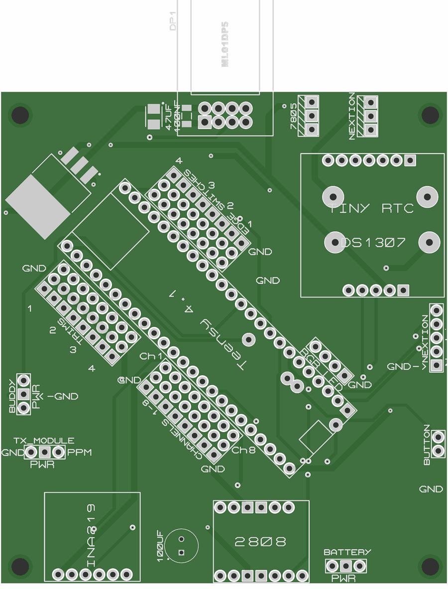
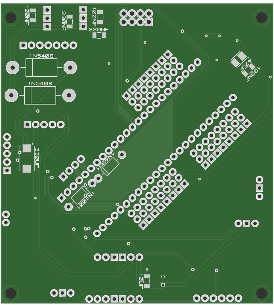
| Circuit board | 2 layers, about 83 × 91 mm, from the Gerber files | 1 | Carries everything else | A PCB maker (Malcolm uses JLCPCB) | – |
|---|
| Teensy 4.1 | PJRC Teensy 4.1 (600 MHz) | 1 | The transmitter's computer: reads the sticks, runs the radio link | PJRC, The Pi Hut, Cool Components | £30 |
|---|
| Radio module | Ebyte E01-ML01DP5 (nRF24L01+ with amplifier) | 1 | The 2.4 GHz radio | Ebyte's own shops | – |
|---|
| Voltage sensor | INA219 breakout module, I2C address 0x40 | 1 | Measures the transmitter's battery | Adafruit, SparkFun, or a compatible module | £5 |
|---|
| Clock | "Tiny RTC" DS1307 module with its coin cell | 1 | Date and time for the logs. The screen sets it from the internet | Electronics shops | – |
|---|
| Power switch | Pololu 2808 pushbutton power switch | 1 | Switches the transmitter on and off. Lets the Teensy switch itself off | Pololu, or a reseller | £5 |
|---|
| 5 V regulators | Pololu S13V10F5 (5 V, 1 A), or a 7805 | 2 | One 5 V supply for the Teensy, one for the screen | Pololu; any electronics shop | – |
|---|
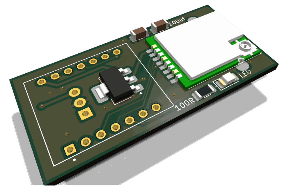
| 3.3 V regulator | AMS1117-3.3 | 1 | 3.3 V for the radio, the sticks and the sensors | Any electronics shop | – |
|---|
| Diodes | 1N5406 × 2, 1N4001 × 2 | 4 | Protect the regulators and the power button's circuit | Any electronics shop | – |
|---|
| Capacitors | Electrolytic: 330 µF, 100 µF. Tantalum: 330 µF (0E907) × 2, 47 µF (1206) × 2. Ceramic, 1206: 330 nF × 2, 100 nF × 4, 10 µF × 1 | 13 | Keep the supplies smooth | Any electronics shop | – |
|---|
| The screen |
|---|
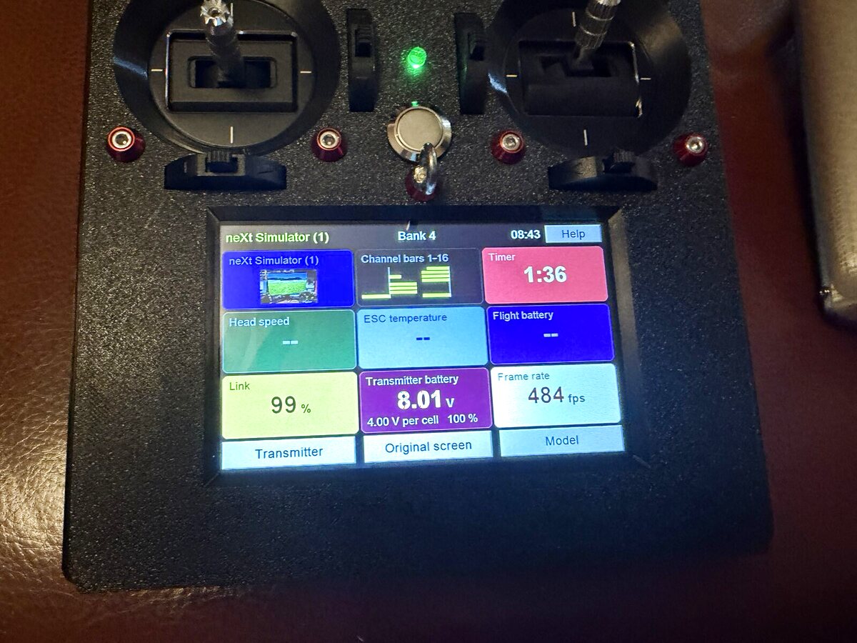
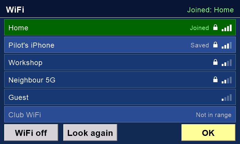
| Touchscreen | Elecrow CrowPanel 5.0" ESP32 HMI, DIS07050H, N4R8 (ESP32-S3, 4 MB flash, 8 MB PSRAM, 800 × 480) | 1 | The pages, WiFi, Bluetooth, sound and updates | Elecrow, RobotShop | £40–£43 |
|---|
| microSD card for the screen | Any size, formatted FAT32 | 1 | Pages, fonts, sounds and pictures. The screen fills it itself | Anywhere | – |
|---|
| Speaker | 8 Ω, 1–2 W (a Nextion's speaker will do); a 4 Ω one is louder | 1 | Voice and sounds. Plugs into the screen's SPK port (2-pin PH2.0) | Electronics shops | – |
|---|
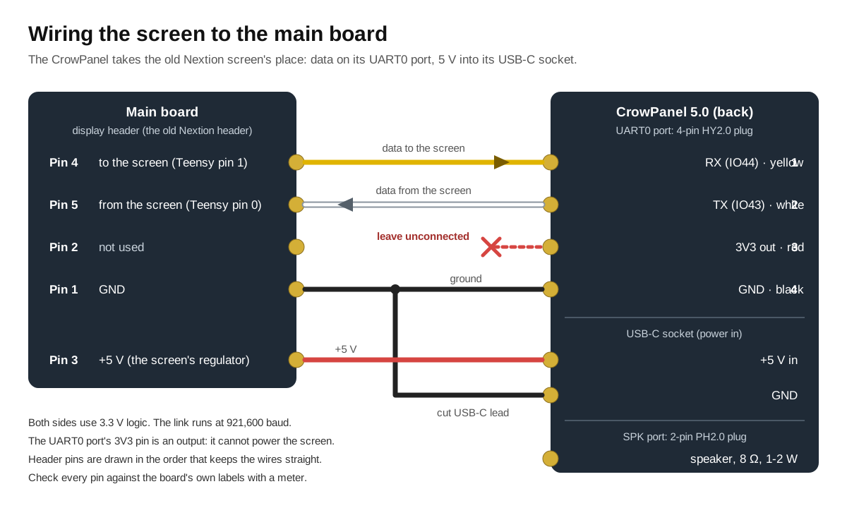
| Screen data lead | HY2.0 4-pin lead ("Grove" style) | 1 | Joins the screen's UART0 port to the main board | Electronics shops | – |
|---|
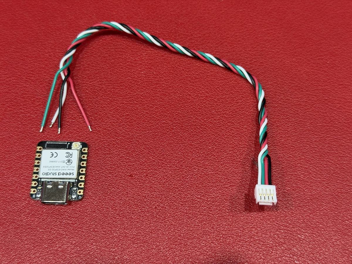
| Screen power lead | A short USB-C lead, its far end cut off | 1 | Takes 5 V from the main board into the screen's USB-C socket | Anywhere | – |
|---|
| Sticks, switches and lights |
|---|
| Sticks | FrSky M9 Hall-sensor gimbals | 2 | The two sticks | FrSky dealers, model shops | £40–£60 a pair |
|---|
| Trims | FrSky trim switches (X9D Plus spare part) | 4 | Digital trims beside the sticks | Model shops | – |
|---|
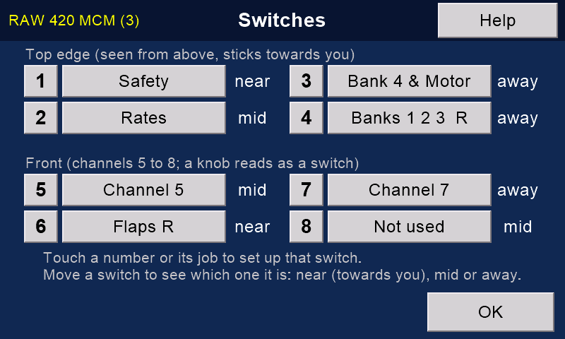
| Top-edge switches | Three-position RC switches | 4 | Safety, banks, rates and more: you choose each one's job | Model shops, electronics shops | – |
|---|
| Front switches or knobs | Three-position switches, or knobs (potentiometers) | 4 | Channels 5 to 8, or any job | Model shops, electronics shops | – |
|---|
| Power button | 16 mm vandal-resistant, momentary push button | 1 | On and off; held at switch-on, it starts binding | Electronics shops | – |
|---|
| Status light | 5 mm RGB LED, common cathode | 1 | Red: trying to connect. Green: connected. Blue: busy | Electronics shops | – |
|---|
| Power and aerial |
|---|
| Battery | 2S pack (two cells): LiPo, Li-ion or LiFePO4 | 1 | Powers the transmitter | Model shops | – |
|---|
| Charger Optional | A 2S balance charger module: micro-USB, or a small USB-C 2S module | 1 | Charges the pack inside the case. Must match the battery type: LiPo/Li-ion or LiFePO4 | Electronics shops | – |
|---|
| Aerial | 2.4 GHz RP-SMA aerial, with a 20 cm RP-SMA male-to-female extension | 1 | Brings the aerial outside the case. Check your radio module's socket before you buy | Electronics shops | – |
|---|
| Cards, wiring and case |
|---|
| microSD card for the Teensy | Any size, FAT32 or exFAT | 1 | Models, logs and the help texts | Anywhere | – |
|---|
| Connectors | Male and female headers, three-row headers, a 2×4 socket (for the radio), servo cable, DuPont 3- and 4-pin connectors | Various | Join the controls to the board | Electronics shops | – |
|---|
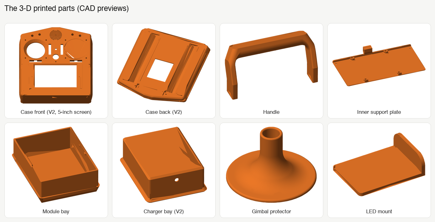
| Case | 3D-printed, in PETG or similar | 1 set | Holds everything | Print it yourself | – |
|---|
| Fixings | Self-tapping screws (3 mm, 2 mm flange), M3 bolts with locknuts, 2 mm cable ties, five-minute epoxy | Various | Hold the case and the parts together | Hardware shops | – |
|---|